A circuit is just a loop — wires connecting a battery to some stuff (a bulb, a motor, a resistor) and back to the battery. Plug a phone charger into the wall and you’ve completed a circuit. Flip a light switch and you’ve completed (or broken) one.
Before you can analyze any circuit on the MCAT, you need to know two basic things: what’s actually moving through the wires, and what’s pushing it. Those are current (the flow of charge) and EMF (the energy source pushing it). Get these two ideas right and the rest of circuit analysis is just bookkeeping.
What Is Electric Current?
Picture a packed school hallway between classes. No single student is sprinting — most are shuffling. But the crowd as a whole moves steadily toward the next class. Electric current works the same way. Individual electrons drift slowly through a wire — often less than a millimeter per second — but the collective movement of trillions of charges per second produces the measurable flow we call current.
Current is a scalar (just magnitude), but we still assign it a direction for circuit analysis — and that’s where the next quirk comes in.
Conventional Current vs. Electron Flow
A weird piece of physics history that the MCAT expects you to know:
When Benjamin Franklin first described electricity in the 1700s, he guessed that positive charges flowed from the + terminal to the − terminal. He guessed wrong. We now know that electrons (negatively charged) actually flow from − to +. But Franklin’s convention got baked into all the math and circuit symbols, and we never bothered to flip it.
So:
Conventional current flows + → − through the external circuit. (This is the convention used in every formula and diagram.)
Electron flow is the opposite: − → +.
On the MCAT, always use conventional current unless the question explicitly asks about electron flow.
The Water-Park Analogy
A simple circuit: a battery provides EMF that drives current through the lamp via the switch. Current flows from + terminal, through the external circuit, back to − terminal. Break the loop anywhere and all current stops. Credit: Wikimedia Commons, CC BY-SA
A complete circuit is a lot like a water park.
Battery = the pump that lifts water to the top of the park (provides energy to the charges).
Wires = wide pipes that carry water with very little resistance.
Resistor = a narrow, twisting slide where water loses energy as it tumbles down (charges lose energy as they pass through).
Crucial rule: water has to return to the pump. If you break the loop (open circuit), nothing flows.
Electromotive Force (EMF)
Despite the misleading name, EMF is not actually a force. It’s a voltage — specifically, the voltage that a battery (or other energy source) provides to push charge around a circuit.
An ideal battery maintains constant EMF no matter how much current flows. Real batteries have internal resistance (covered in §6.5), which eats up some of the energy and reduces the voltage available to the rest of the circuit.
Requirements for Current to Flow
For steady current to actually exist, you need both:
A complete (closed) loop. Any break anywhere stops all current — not just at the break. This is exactly why a single burned-out bulb in a series string of holiday lights kills the whole strand.
A source of EMF. Something has to do work on the charges to keep them moving. Without a battery (or generator, or solar cell), any current would die out within microseconds as charges lose energy to resistance.
Worked Example
A wire carries a current of 0.5 A. How many coulombs of charge pass a given cross-section in 1 minute? How many electrons is that?
Charge: Q=It=0.5×60=30 C.
Each electron carries 1.6×10⁻¹⁹ C, so number of electrons =30/(1.6×10−19)≈1.9×1020 electrons.
That’s almost 1020 electrons per minute through a wire carrying just half an amp. Even a small current involves an unimaginable number of electrons.
If 15 coulombs of charge pass through a wire in 5 seconds, what is the current?
Click to reveal answer
I=ΔQ/Δt=15/5=3 A.
In which direction does conventional current flow through the external circuit — from + to − or from − to +?
Click to reveal answer
From + to − through the external circuit. Conventional current goes + → external circuit → − terminal. Electrons actually move the opposite way (− to +), but the MCAT uses conventional current unless told otherwise.
A 12 V battery supplies 240 J of energy to a circuit. How much charge passed through?
Click to reveal answer
20 C.ε=W/Q → Q=W/ε=240/12=20 C. The battery did 12 J of work on every coulomb that passed through.
If current is the flow of charge, resistance is what opposes that flow. Every material resists current to some degree. Copper barely fights it (great conductor — that’s why your wires are copper). Rubber fights it almost completely (great insulator — that’s why the wires are coated with rubber).
Understanding resistance and its relationship to voltage and current — captured by Ohm’s law — is the single most important skill for MCAT circuit problems. Ohm’s law shows up in 90% of circuit questions, often in disguise.
Resistance: The Opposition to Flow
Think of resistance as a narrow section of pipe in our water-park analogy. A narrow, long, twisty pipe is hard to push water through. A short, wide, straight pipe is easy. Same idea for charges in a wire.
When charges fight their way through a resistor, they lose energy — that energy becomes heat. This is exactly why phone chargers, laptops, light bulbs, and toaster elements all warm up: the resistance of the circuit is dissipating electrical energy as thermal energy.
This formula gets tested heavily — the MCAT loves to change one variable and ask what happens:
Double the length → resistance doubles (R∝L).
Double the cross-sectional area → resistance halves (R∝1/A).
Switch to a higher-resistivity material → resistance goes up (R∝ρ).
Ohm’s Law
This is the single most-used equation in circuit physics.
Ohm’s law tells you three different things depending on which form you use:
V=IR — The voltage drop across a resistor equals the current times the resistance.
I=V/R — More voltage drives more current; more resistance reduces it.
R=V/I — Resistance is the ratio of voltage drop to current.
Temperature Dependence of Resistance
For metals (conductors), resistance increases as temperature increases. Higher temperature → metal atoms vibrate more → more collisions with the drifting electrons. It’s like trying to walk through a crowd where everyone is dancing chaotically — the more they move, the harder it is to get through.
For semiconductors (silicon, germanium), the opposite is true: resistance decreases as temperature increases. The thermal energy frees up extra charge carriers that more than make up for the increased atomic vibration.
Ohmic vs. Non-Ohmic Materials
An ohmic material obeys Ohm’s law: its resistance stays constant regardless of the voltage applied. On a V vs. I graph, an ohmic material produces a straight line through the origin — and the slope of that line is R.
A non-ohmic material has resistance that changes with voltage or current. Examples:
Diodes — only conduct in one direction; almost no current in the other direction.
Light bulb filaments — heat up sharply when current flows, raising R as they warm.
Batteries under heavy load — internal resistance changes as the battery drains.
The MCAT defaults to assuming resistors are ohmic unless the passage explicitly says otherwise.
Worked Example
A copper wire has resistance 5 Ω. You replace it with a piece of the same copper but twice as long and half the cross-sectional area. What’s the new resistance?
R∝L/A.
Length doubles → factor of 2.
Area halves → factor of 2 (since R is inversely proportional to A).
Combined: Rnew=5×2×2=20 Ω.
A wire has resistance R. If you double its length and triple its cross-sectional area, what is the new resistance in terms of R?
Click to reveal answer
Rnew=2R/3. From R=ρL/A: doubling L doubles resistance, tripling A divides resistance by 3. Net: R×2/3.
A 12 V battery is connected across a 4 Ω resistor. What current flows through the resistor?
Click to reveal answer
I=V/R=12/4=3 A. Direct application of Ohm's law.
A circuit element shows a non-linear V vs. I graph. Is it ohmic or non-ohmic?
Click to reveal answer
Non-ohmic. Ohmic materials have a *constant* resistance, which produces a *straight line* through the origin on a V vs. I graph (slope = R). A non-linear graph means R changes with current/voltage — typical of diodes, hot filaments, or any temperature-dependent component.
When resistors are lined up end-to-end so that all the current must pass through every one of them, they’re in series. This is the simplest circuit configuration and the first one to master — once you nail series, parallel and combinations become much easier to reason about.
The defining feature of series: there’s only one path for current to take. No branching, no shortcuts, no alternate routes.
The Series Rules
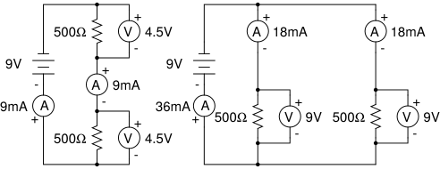
Series vs. parallel resistor configurations. In series, all current flows through every resistor (same current, voltages add). In parallel, current splits among branches (same voltage, currents add). Recognizing which configuration you’re dealing with is the first step in any circuit problem. Credit: Wikimedia Commons, CC BY-SA
Picture three narrow water-park slides connected one after another. All the water entering slide 1 must flow through slide 2 and then slide 3. None of it can take a shortcut. That’s the defining property of a series circuit:
The current is the same through every resistor in series.
Since the same current flows through every resistor, Ohm’s law tells us each resistor drops a voltage proportional to its resistance:
V1=IR1, V2=IR2, V3=IR3.
Those voltage drops have to add up to the total voltage supplied by the battery:
Vtotal=V1+V2+V3+…
This is conservation of energy: every coulomb of charge gets some energy from the battery, then “spends” it dropping through each resistor before returning to the battery.
The Voltage Divider
When the MCAT gives you a series circuit and asks for the voltage across one specific resistor, use the voltage divider formula:
Example. A 12 V battery is connected to a 2 Ω and a 4 Ω resistor in series. Rtotal=6 Ω.
Voltage across 4 Ω: 12×(4/6)=8 V.
Voltage across 2 Ω: 12×(2/6)=4 V.
Check: 8+4=12 V. ✓
The bigger resistor “hogs” more of the voltage drop, in direct proportion to its share of the total resistance.
Interactive Circuit Explorer
🎯 Predict First
Two resistors are in series with a battery. You double the resistance of the FIRST resistor. What happens to the current through the SECOND resistor?
Use this simulation to build series and parallel circuits. Adjust resistor values and battery voltage, then watch current flow and voltage distributions update in real time. Toggle between series and parallel to see how the same resistors behave completely differently.
Rtotal 30.00 ΩItotal 0.40 APtotal 4.80 W
R1 = 10 ΩV = 4.00 VI = 0.40 AP = 1.60 W
R2 = 20 ΩV = 8.00 VI = 0.40 AP = 3.20 W
Series: same current through all resistors; voltage divides proportional to R.
Series Circuit Summary
| Property | Series rule |
|----------|-------------------|
| Current | Same through all resistors |
| Voltage | Divides among resistors (V=IR for each) |
| Total resistance | Rtotal=R1+R2+… (sums up) |
| If one resistor breaks (open) | Entire circuit stops — no current anywhere |
Three resistors (3 Ω, 5 Ω, 2 Ω) are connected in series to a 20 V battery. What is the current in the circuit and the voltage across the 5 Ω resistor?
Click to reveal answer
I=2 A; V5Ω=10 V.Rtotal=3+5+2=10 Ω. I=V/R=20/10=2 A. Voltage across 5 Ω: V=IR=2×5=10 V. (Or by voltage divider: 20×(5/10)=10 V.)
Two resistors are in series. The voltage across the first is three times the voltage across the second. If R2=4 Ω, what is R1?
Click to reveal answer
R1=12 Ω. Same current through both, so V∝R. V1=3V2⇒R1=3R2=12 Ω.
Four identical 5 Ω resistors are connected in series to a 10 V battery. What is the current through each resistor?
Click to reveal answer
0.5 A through every resistor.Rtotal=4×5=20 Ω. I=V/R=10/20=0.5 A. Same current flows through all four — that’s the defining feature of series.
When resistors are connected so that each one provides a separate path for current, they’re in parallel. Parallel circuits behave very differently from series circuits, and the MCAT tests these differences relentlessly.
The defining feature of parallel: there are multiple paths current can take. Each resistor has its own branch.
The Parallel Rules
Picture the water park installing three slides side-by-side, all starting at the same upper pool and ending at the same lower pool. Each slide is a separate path. Water splits up among the three slides — but every slide starts and ends at the same elevation. That’s a parallel circuit.
The voltage is the same across every resistor in parallel.
This makes intuitive sense: adding another slide (even a narrow one) gives water more paths, so total flow goes up and total opposition goes down.
Current Division
Since every resistor has the same voltage across it, Ohm’s law tells you that more current flows through smaller resistors:
I1=V/R1, I2=V/R2, I3=V/R3.
Total current: Itotal=I1+I2+I3+….
The Product-Over-Sum Shortcut
For exactly two resistors in parallel, there’s a much faster formula than the reciprocal one:
This only works for two resistors. For three or more, you need the reciprocal formula (or pair them up two at a time).
N Equal Resistors in Parallel
When N identical resistors (each R) are in parallel, the formula simplifies beautifully:
Parallel Circuit Summary
Property
Parallel rule
Voltage
Same across all resistors
Current
Divides among branches (I=V/R each)
Total resistance
1/Rtotal=∑1/Ri (always less than the smallest)
If one resistor breaks (open)
Other branches keep working
Series vs. Parallel: The One Table to Remember
Series
Parallel
Same value across all resistors
Current
Voltage
Adds together
Resistance, voltage
Currents
Total compared to individuals
Bigger than any
Smaller than any
One bulb burns out
All go dark
Others keep working
If you internalize this contrast, series-and-parallel problems become almost mechanical.
A 6 Ω and a 12 Ω resistor are in parallel across a 12 V battery. What is the total resistance and the current through each resistor?
Click to reveal answer
Rtotal=4 Ω; currents: 2 A through 6 Ω, 1 A through 12 Ω. Product-over-sum: (6×12)/(6+12)=72/18=4 Ω. Both resistors see 12 V. I6=12/6=2 A; I12=12/12=1 A. Total: 3 A. Check: V/Rtotal=12/4=3 A. ✓
Three 9 Ω resistors are connected in parallel. What is the equivalent resistance?
Click to reveal answer
3 Ω.N equal resistors in parallel: Rtotal=R/N=9/3=3 Ω.
Two resistors are in parallel. One carries 4× as much current as the other. If R1=12 Ω, what is R2?
Click to reveal answer
R2=3 Ω. Same voltage across both, so I∝1/R. If I2=4I1, then R2=R1/4=12/4=3 Ω. The smaller resistor carries more current — exactly what parallel division predicts.
There’s no such thing as an ideal battery. Every real battery has some internal resistance — a small but real opposition to current inside the battery itself. That resistance steals a portion of the EMF before any current reaches the external circuit, which is why your phone charger feels warm and why old batteries can no longer power what they once could.
The MCAT requires you to understand this concept and the formula that goes with it. Without internal resistance, every battery would deliver its full rated voltage forever — but then we couldn’t explain why an old AA can’t run a toy any longer despite having “almost full” voltage when measured.
Terminal Voltage
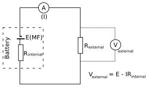
A real battery modeled as an ideal EMF source (ε) in series with internal resistance r. The terminal voltage available to the external circuit is V=ε−Ir. As current grows, more voltage is lost inside the battery. Credit: Wikimedia Commons, CC BY-SA
Think of a real battery as a tiny circuit inside itself: an ideal EMF source in series with a small internal resistance r. When current flows, some voltage gets “lost” inside the battery — converted to heat by the internal resistance. The voltage you actually measure at the battery’s terminals is less than the EMF.
When no current flows (open circuit), the terminal voltage equals the EMF exactly — because the Ir drop is zero. This is why a voltmeter reading across an unused battery shows the full EMF (a voltmeter draws negligible current).
Why Batteries “Die”
As a battery ages, its internal resistance increases due to chemical degradation inside the cell. The Ir drop gets bigger and bigger, leaving less voltage for the external circuit. The battery’s EMF may still be close to its rated value — but so much voltage gets lost internally that the device can’t function any more.
This is why an “old” AA battery often shows nearly full voltage on a multimeter (where almost no current is drawn) but can’t power a flashlight (which needs to draw real current). Multimeter sees ~1.5 V open-circuit; flashlight sees, say, 0.6 V because Ir has eaten the rest.
The Complete Circuit Equation
For a simple circuit with a battery (EMF ε, internal resistance r) and an external resistance R:
So the terminal voltage across the external resistor is:
Vterminal=IR=R+rεR
When R≫r (external resistance much larger than internal): nearly all the EMF appears across the external resistor (negligible internal loss). When R≪r (small external resistor): most of the EMF gets dropped inside the battery.
Short Circuits
A short circuit is when the external resistance approaches zero — a bare wire connects the battery terminals directly, with no load in between. In that case:
Ishort=rε
This is the maximum possible current the battery can deliver. All the EMF drops across the internal resistance, dumping massive power into the battery as heat. In real life, short circuits are dangerous — batteries can rupture or catch fire, lithium-ion cells in particular can vent flames. (Hence safety circuits in modern devices.)
A battery has EMF 9 V and internal resistance 0.5 Ω. It's connected to a 4 Ω external resistor. What is the terminal voltage?
Click to reveal answer
Vterminal=8 V. Current: I=ε/(R+r)=9/4.5=2 A. Terminal: V=ε−Ir=9−2(0.5)=8 V (or directly: V=IR=2×4=8 V).
A 12 V battery with internal resistance 2 Ω is short-circuited. What is the current?
Click to reveal answer
I=6 A. In a short, R=0, so I=ε/r=12/2=6 A. All 12 V drops across the internal resistance, dumping P=εI=72 W of heat into the battery — which is exactly why shorts are dangerous.
An old AA battery shows 1.5 V on a multimeter (open circuit) but only 0.5 V when connected across a small flashlight bulb that draws 0.5 A. What is the internal resistance?
Click to reveal answer
r=2 Ω. Voltage drop inside the battery: ε−Vterminal=1.5−0.5=1 V. This drop equals Ir, so r=(1 V)/(0.5 A)=2 Ω. (A new AA usually has r≈0.1–0.3 Ω. This battery has aged and degraded — the bigger r is what makes it "dead.")
Series and parallel rules handle simple circuits beautifully. But what about messier ones — circuits with multiple batteries, branching paths, or components that don’t fit neatly into “series” or “parallel” boxes? That’s where Kirchhoff’s two laws come in.
These aren’t new physics. They’re just conservation of charge and conservation of energy applied specifically to circuits — dressed up in slightly intimidating names. Understand the analogies and the laws become almost obvious.
Kirchhoff’s Current Law (KCL) — The Junction Rule
This is just conservation of charge. Charges can’t pile up at a junction or disappear — whatever flows in has to flow out.
Think of a river fork: if 10 m³/s flows into the fork and 6 m³/s goes left, then 4 m³/s must go right. The water didn’t vanish, and it didn’t accumulate at the split.
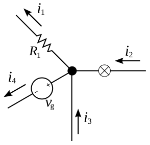
Kirchhoff's junction rule (KCL): the total current flowing into a node equals the total current flowing out. No charge accumulates at a junction. Credit: Wikimedia Commons, CC BY-SA
Example. If 5 A flows into a junction and splits into three branches with 2 A in the first branch and 1 A in the second, the third branch carries 5−2−1=2 A out.
Kirchhoff’s Voltage Law (KVL) — The Loop Rule
This is conservation of energy. A charge that travels around a complete loop and returns to its starting point ends up with the same potential energy it started with — so the energy gained from batteries must exactly equal the energy lost across resistors. Net change: zero.
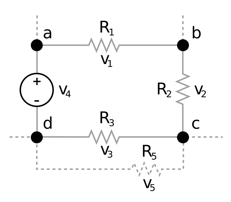
Kirchhoff's loop rule (KVL): voltage gains and drops around any closed loop sum to zero. Energy gained from batteries equals energy lost across resistors. Credit: Wikimedia Commons, CC BY-SA
Sign Conventions for KVL
When you “walk” around a loop in a chosen direction, here’s how to tally up voltage changes:
Element
Walking direction
Voltage change
Battery
− to + (through the battery)
+ε (gain)
Battery
+ to − (through the battery)
−ε (drop)
Resistor
Same direction as current
−IR (drop)
Resistor
Against direction of current
+IR (gain)
The choice of loop direction doesn’t matter — pick one, stay consistent, and the math works out.
Applying Kirchhoff’s Laws — A Strategy
Label all currents with assumed directions. If you guess wrong, the math returns a negative value — that just means the current actually flows opposite your guess. No need to redo the diagram.
Apply KCL at each junction to relate the branch currents.
Apply KVL around enough independent loops to solve for all unknowns.
Solve the system of equations.
For the MCAT, you rarely need more than one junction equation and one or two loop equations. The exam favors conceptual understanding over algebraic complexity.
Quick Example
A simple loop has a 10 V battery and two series resistors: R1=3 Ω and R2=2 Ω. Apply KVL clockwise starting at the battery:
+10 V−I(3)−I(2)=0
10=5I⇒I=2 A. Then VR1=6 V, VR2=4 V. They add to 10 V — the battery’s EMF. KVL satisfied. ✓
This tiny example shows the recipe: walk around the loop, write down each voltage change with the correct sign, set the sum to zero, solve.
At a junction, 8 A flows in from one wire. Two wires leave carrying 3 A and 2 A. A third wire also leaves. What current does it carry?
Click to reveal answer
3 A out. KCL: Iin=Iout⇒8=3+2+I3⇒I3=3 A.
A loop contains a 15 V battery, a 4 Ω resistor, and an unknown resistor R. Current in the loop is 3 A. What is R?
Click to reveal answer
R=1 Ω. KVL: 15−3(4)−3R=0⇒15−12=3R⇒R=1 Ω. Voltage drops: 12 V across the 4 Ω + 3 V across the 1 Ω = 15 V battery EMF. ✓
In a loop containing a 12 V battery and three resistors in series, the voltage drops across two of the resistors are 4 V and 5 V. What is the voltage drop across the third?
Click to reveal answer
3 V. KVL: voltage drops must sum to the battery EMF. 12−4−5−V3=0⇒V3=3 V. No need to know the resistance values — just the loop conservation.
Power in a circuit tells you how fast electrical energy is being converted into other forms — usually heat (toaster, hair dryer), light (bulb), or motion (motor). When you pay your electricity bill, you’re literally paying for power × time = energy.
The MCAT tests circuit power with three equivalent formulas. The trick isn’t memorizing any one of them — it’s knowing which form to reach for depending on what the question gives you.
The Three Power Formulas
When to use each:
P=IV — when you know current and voltage directly.
P=I2R — when you know current and resistance. Common in series circuits, where current is the same through every resistor.
P=V2/R — when you know voltage and resistance. Common in parallel circuits, where voltage is the same across every resistor.
Brightness of Bulbs
The MCAT loves asking which bulb in a circuit is brightest. The rule is simple:
Brightness ∝ power dissipated by the bulb.
But which power formula to use depends on the configuration:
In a series circuit, all bulbs carry the same current. So P=I2R — the bulb with the highest resistance is brightest.
In a parallel circuit, all bulbs see the same voltage. So P=V2/R — the bulb with the lowest resistance is brightest.
Energy Dissipated
Power is energy per unit time. To find total energy dissipated by a resistor over a time t:
This is exactly how electricity bills work — you pay for energy in kilowatt-hours (kWh), not power. A 100 W bulb running 10 hours = 1 kWh ≈ 15¢.
RMS Values (AC Circuits)
The MCAT occasionally touches on alternating current (AC). In AC circuits, voltage and current oscillate sinusoidally — they’re constantly changing direction. To get a meaningful “average” power, we use root-mean-square (RMS) values.
The average power dissipated in an AC circuit uses RMS values: Pavg=IrmsVrms=Irms2R.
Two identical bulbs are connected in series to a battery. A third identical bulb is connected directly across the same battery (in parallel with the series pair). Which single bulb is brightest?
Click to reveal answer
The single bulb in parallel is brightest. The single bulb gets the full battery voltage. The two series bulbs split the voltage, so each gets half. Since P=V2/R and all bulbs have the same R, the one with the full voltage dissipates the most power.
An AC source has peak voltage 170 V. What's the RMS voltage? If connected to a 100 Ω resistor, what's the average power dissipated?
Click to reveal answer
Vrms=120 V; Pavg=144 W.Vrms=170/2≈120 V. P=Vrms2/R=14,400/100=144 W. (This is exactly a US wall-outlet circuit driving a 100 Ω resistor.)
A 1500 W microwave runs for 5 minutes. How much energy does it use, in joules and in kWh?
Click to reveal answer
450,000 J = 0.125 kWh.E=Pt=1500×300=450,000 J. In kWh: 1.5×(5/60)=0.125 kWh — about 2 cents of electricity.
Resistors dissipate energy (turn it into heat). Capacitors store energy — and release it later, on demand.
A camera flash is the textbook example. The battery slowly trickles charge into a capacitor over a couple of seconds. Then, when you press the shutter, the capacitor dumps all that stored energy in less than a millisecond — producing a brilliant burst of light far brighter than the battery alone could deliver. Same total energy as the battery provided, just released at a much higher rate.
The same physics powers defibrillators (slow charge from a battery, sudden discharge through a patient’s chest), camera flashes, audio amplifiers (capacitors smooth out the power supply), and the timing circuits in nearly every electronic device.
What Is a Capacitor?
At its simplest, a capacitor is just two conducting plates separated by a small gap. When connected to a battery, positive charge piles up on one plate and negative charge on the other. The plates don’t touch, so charge can’t flow between them — it just builds up, creating an electric field across the gap.
Capacitance
Capacitance measures how much charge a capacitor stores per volt applied.
Parallel Plate Capacitor
The most common capacitor geometry on the MCAT is the parallel plate capacitor: two flat plates of area A separated by distance d.
The MCAT loves “what happens when you change one variable” questions:
Double the plate area → capacitance doubles (C∝A).
Double the plate separation → capacitance halves (C∝1/d).
Insert a dielectric → capacitance increases by a factor κ (covered in §6.10).
The Electric Field Between the Plates
The electric field between the plates of a parallel plate capacitor is uniform (constant everywhere) and given by:
E=dV
So field strength grows when voltage grows or plate separation shrinks. This uniform field is exactly why parallel plate capacitors are the go-to setup for MCAT problems about charged particles flying through electric fields — the math is much simpler with a uniform field than with the messy fields around point charges.
Energy Stored in a Capacitor
A charged capacitor stores electrical potential energy in the electric field between its plates.
That 21 factor isn’t arbitrary. The voltage builds gradually as the capacitor charges. The first bit of charge is easy to add (low voltage opposing it), but the last bit has to push against the high voltage that’s already built up. Average voltage during the charging process is half the final voltage — hence the 21.
A parallel plate capacitor has plate area A and separation d. If the separation is tripled (battery stays connected), what happens to the capacitance and the energy stored?
Click to reveal answer
Capacitance drops to C/3; energy drops to U/3.C=ε0A/d, so tripling d cuts C by 3. With the battery connected, V stays constant. U=21CV2 drops by the same factor of 3.
A 5 μF capacitor is charged to 200 V. How much energy is stored?
Click to reveal answer
0.1 J (100 mJ).U=21CV2=21(5×10⁻⁶)(2002)=21(5×10⁻⁶)(40,000)=0.1 J.
A 100 μF defibrillator capacitor stores 360 J of energy. To what voltage was it charged?
Click to reveal answer
About 2680 V.U=21CV2⇒V=2U/C=2(360)/(100×10−6)=7.2×106≈2683 V. (Defibrillators really do operate at thousands of volts to deliver enough energy to restart a heart in a few milliseconds.)
Here’s one of the most reliable traps the MCAT sets: capacitors combine in the exact opposite way from resistors.
If you memorize the resistor combination rules and then blindly apply them to capacitors, you’ll get every capacitor problem wrong. This section exists to make sure that never happens.
The rules to lock in:
Resistors in series add directly. Capacitors in series use reciprocal addition.
Resistors in parallel use reciprocal addition. Capacitors in parallel add directly.
The pattern is exactly reversed. Once you internalize “capacitors are contrary,” every capacitor combination problem becomes mechanical.
Capacitors in Parallel
When capacitors are connected in parallel, they all share the same voltage (just like parallel resistors). But for the capacitances, you add directly — not reciprocally.
Why does this make sense? Each parallel capacitor stores its own charge independently. Total charge stored: Qtotal=Q1+Q2+Q3. They all share the same voltage V, so:
Ctotal=VQtotal=VQ1+Q2+Q3=C1+C2+C3
Capacitors in Series
When capacitors are connected in series, the same chargeQ ends up on each capacitor (the inner connected plates have nowhere else for charge to go — it gets stuck between the plates of adjacent capacitors). The voltages then add up.
For exactly two capacitors in series, you can use the same product-over-sum shortcut you learned for parallel resistors:
Ctotal=C1+C2C1⋅C2
The Opposite-of-Resistors Rule
The full lookup table, all in one place:
Configuration
Resistors
Capacitors
Series
Rtotal=R1+R2 (direct)
1/Ctotal=1/C1+1/C2 (reciprocal)
Parallel
1/Rtotal=1/R1+1/R2 (reciprocal)
Ctotal=C1+C2 (direct)
Why the Reversal Makes Physical Sense
Think about parallel-plate capacitors:
Adding capacitors in parallel is like increasing the total plate area. More area = more charge storage = more capacitance. So adding directly makes sense.
Adding capacitors in series is like increasing the separation between the outermost plates. Bigger separation = less capacitance (C∝1/d). So putting them in series reduces total capacitance — and the reciprocal addition reflects that.
This physical intuition matches the math exactly.
Worked Example
A 6 μF and a 3 μF capacitor are connected in parallel; that combination is then put in series with a 4 μF capacitor. What is the total capacitance?
Parallel pair first:C12=6+3=9 μF.
Then in series with 4 μF:Ctotal=(9×4)/(9+4)=36/13≈2.77 μF.
Notice the answer (~2.77 μF) is smaller than the smallest capacitor (3 μF) — that’s the series step doing its work. If we’d done the operations in the wrong order, the answer would be very different.
A 4 μF and a 12 μF capacitor are in series. What is the equivalent capacitance?
Click to reveal answer
3 μF. Product-over-sum: Ctotal=(4×12)/(4+12)=48/16=3 μF. Notice 3 μF is less than both individual capacitors — series always shrinks total capacitance.
Three capacitors (2 μF, 3 μF, 5 μF) are connected in parallel. What is the equivalent capacitance?
Click to reveal answer
10 μF. Capacitors in parallel add directly: Ctotal=2+3+5=10 μF. Total is larger than any individual capacitor.
Three identical 6 μF capacitors are arranged so two are in parallel, and that combination is in series with the third. What's the equivalent capacitance?
Click to reveal answer
4 μF. Parallel pair: Cp=6+6=12 μF. Series with the third 6 μF: Ctotal=(12×6)/(12+6)=72/18=4 μF.
A dielectric is an insulating material placed between the plates of a capacitor. Glass, plastic, ceramic, paper, even air — all are dielectrics. They’re called “insulators” in everyday speech (because they don’t conduct), but in capacitor land they have a special name and a specific job.
Inserting a dielectric always increases capacitance. But the downstream effects — what happens to voltage, charge, and energy — depend on whether the battery is still connected. This distinction is one of the highest-yield topics in MCAT circuit physics. The exam loves writing both versions of the question and watching students get one right and the other wrong.
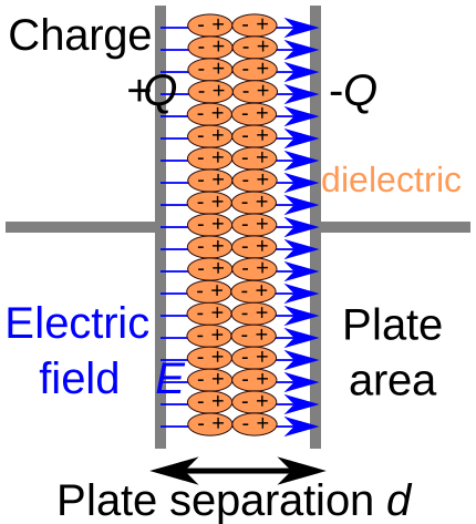
A capacitor with a dielectric inserted. The dielectric molecules polarize in the electric field, partially canceling the internal field — which lets the capacitor store more charge at the same voltage. Credit: Wikimedia Commons, CC BY-SA
How Dielectrics Increase Capacitance
Why Does This Happen?
The dielectric molecules can polarize — their positive and negative ends shift slightly in response to the electric field between the plates. The polarized molecules create their own small internal electric field that points opposite to the original field. The two fields partially cancel, leaving a weaker net field.
A weaker field means less voltage is needed to support a given amount of charge — equivalently, more charge can be stored at the same voltage. That’s exactly what “higher capacitance” means.
The Two Scenarios: Battery Connected vs. Disconnected
This is where the MCAT gets sneaky. You have to know what stays constant in each scenario.
Scenario 1: Battery Stays Connected
The battery enforces constant voltage across the capacitor.
Quantity
What happens
Why
Capacitance (C)
× κ
C=κC0
Voltage (V)
Stays the same
Battery holds it
Charge (Q)
× κ
Q=CV, V constant, C bigger
Electric field (E)
Stays the same
E=V/d, V and d unchanged
Energy (U)
× κ
U=21CV2, V constant, C bigger
Scenario 2: Battery Disconnected, Then Dielectric Inserted
The charge is trapped on the plates — no battery to add or remove any.
Quantity
What happens
Why
Capacitance (C)
× κ
C=κC0
Charge (Q)
Stays the same
No battery to change it
Voltage (V)
÷ κ
V=Q/C, Q constant, C bigger
Electric field (E)
÷ κ
E=V/d, V smaller
Energy (U)
÷ κ
U=Q2/(2C), Q constant, C bigger
Dielectric Breakdown
Every dielectric has a maximum electric field strength it can withstand. Push above this limit (called the dielectric strength) and the material suddenly starts conducting — the capacitor discharges all at once, often destructively.
The most familiar example: lightning. The atmosphere is normally a great insulator (air’s dielectric strength is ~3 MV/m). But during a storm, charge separation builds up such enormous voltages between cloud and ground that the field exceeds air’s breakdown strength. Air abruptly becomes conducting along a path → boom, lightning bolt.
The same principle limits how small modern electronics can be: as components shrink, fields get bigger (E=V/d), and engineers have to choose dielectrics with very high breakdown strengths to avoid catastrophic failure.
A parallel plate capacitor is connected to a 100 V battery. A dielectric with κ=4 is inserted. What happens to the charge on the plates?
Click to reveal answer
Charge increases by a factor of 4. Battery stays connected, so V is constant. C increases to 4C0. Q=CV, so Q increases to 4Q0. The battery pushes additional charge onto the plates to maintain the same voltage.
A charged capacitor is disconnected from the battery. A dielectric (κ=3) is then inserted. What happens to the voltage and the energy stored?
Click to reveal answer
Voltage drops to V0/3; energy drops to U0/3. Battery disconnected, so Q is constant. C increases to 3C0. V=Q/C → V drops by 3. U=Q2/(2C) → U drops by 3. The "missing" energy went into pulling the dielectric into the gap (the field literally pulls the dielectric in — work that energy did).
Why does inserting a dielectric *always* increase capacitance, regardless of which scenario you're in?
Click to reveal answer
Because C depends only on geometry and material — not on V or Q. The dielectric polarizes in the field, partially canceling the field inside the gap. That allows more charge to be stored per volt — a higher C. The increase happens whether or not a battery is present, because C is a property of the capacitor itself, not of the circuit it's in.
This section covers two AAMC-listed topics that often share the same MCAT passage: how materials conduct electricity, and how we measure current and voltage without messing up the very circuit we’re trying to study.
The conductivity material connects physics to general chemistry (electrolytes), and the meter material connects to lab-skills questions. Both are bite-sized topics with high test-yield-per-page-of-prep.
Conductivity
Conductivity is the inverse of resistivity. Where resistivity tells you how much a material opposes current, conductivity tells you how easily current flows.
Two Types of Conduction
The MCAT distinguishes between two fundamentally different ways charge can move through a material.
Metallic Conduction
In metals like copper or silver, the charge carriers are free electrons — a “sea” of delocalized electrons that aren’t tied to specific atoms. When a voltage is applied, those electrons drift toward the positive terminal.
Key features:
Charge carriers: electrons.
Conductivity decreases as temperature rises (more atomic vibrations means more collisions with the drifting electrons).
No chemical change in the conductor — it’s a physical process.
Electrolytic Conduction
In ionic solutions (NaCl in water, sulfuric acid, biological fluids), the charge carriers are ions — both positive cations moving one way and negative anions moving the other.
Key features:
Charge carriers: dissolved ions.
Conductivity increases as temperature rises (ions move faster, may dissociate more).
Conductivity increases with ion concentration.
Chemical changes can occur at electrodes (this is electrolysis — the basis of car batteries, electroplating, electrolytic cells in chemistry).
Ammeters and Voltmeters
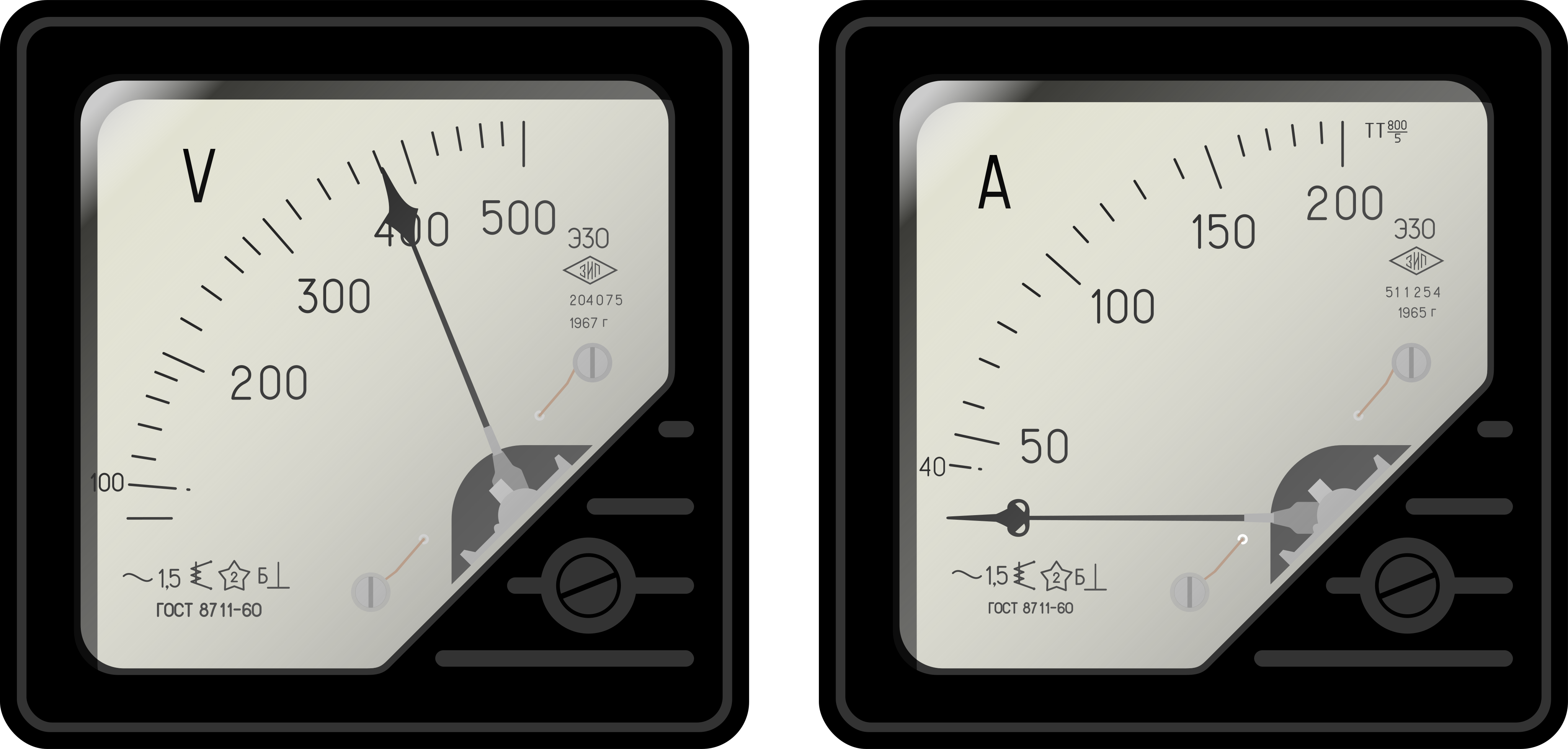
Proper placement of meters. The ammeter (A) goes in series so all current passes through it. The voltmeter (V) goes in parallel to measure potential difference across the resistor without diverting significant current. Credit: Wikimedia Commons, CC BY-SA
Ammeters: Measuring Current
An ammeter measures current and must be placed in series with the component you’re measuring. All the current you’re measuring has to flow through the ammeter.
For an ammeter to avoid disturbing the circuit, it must have very low internal resistance (ideally zero). If the ammeter had high resistance, it would behave like an extra resistor in series, reducing the very current you were trying to measure.
Voltmeters: Measuring Voltage
A voltmeter measures the potential difference between two points and must be placed in parallel with the component you’re measuring.
For a voltmeter to avoid disturbing the circuit, it must have very high internal resistance (ideally infinite). If the voltmeter had low resistance, it would provide an alternate current path through itself, changing the circuit’s behavior.
Meter
Connection
Ideal resistance
Why
Ammeter
Series
≈ 0 Ω
Doesn’t add resistance to the loop
Voltmeter
Parallel
≈ ∞ Ω
Doesn’t draw current from the circuit
What Happens with Non-Ideal Meters?
A real ammeter has some small resistance (not zero). It reduces the current in the circuit slightly. The measured current is lower than the true value would be without the ammeter present.
A real voltmeter has finite (not infinite) resistance. It draws a tiny bit of current through itself, which slightly changes the voltage distribution in the circuit. The measured voltage is lower than the true value would be.
In practice, both effects are usually negligible because modern meters approach ideal behavior closely enough — but the MCAT may test the concept.
You want to measure the current through a resistor and the voltage across it. Where do you connect the ammeter and the voltmeter?
Click to reveal answer
Ammeter in series with the resistor (all current passes through it). Voltmeter in parallel across the resistor (measures the potential difference at its two ends). Ammeter should have near-zero resistance; voltmeter should have near-infinite resistance.
How does increasing temperature affect the conductivity of a copper wire vs. a saltwater solution?
A student accidentally connects an ammeter in *parallel* with a small resistor instead of in series. What happens?
Click to reveal answer
A near-short circuit. Huge current flows through the ammeter. The ammeter has near-zero resistance, so connecting it in parallel with another resistor effectively short-circuits that resistor. Almost all the current flows through the ammeter (which can damage it), and the original circuit dynamics are completely disrupted. This is why ammeters are designed never to be connected in parallel.
An RC circuit contains a resistor (R) and a capacitor (C). When you flip a switch, the capacitor doesn’t charge or discharge instantly — it does so gradually, following an exponential curve. The resistor sets the pace; the capacitor sets the size of the storage.
The MCAT doesn’t ask you to derive the exponential equations, but you must know the qualitative behavior and the time constantτ=RC. RC circuits show up everywhere: camera flashes, defibrillators, audio filters, the timing circuits in just about every electronic device.
This section also wraps up the chapter with a general circuit-problem-solving strategy that you can apply to anything from simple series/parallel questions to multi-loop monsters.
Charging an RC Circuit
When a battery is connected to a resistor and an uncharged capacitor in series, charge flows onto the capacitor plates. At first the capacitor is empty, so nothing opposes the current — initial current is high. As charge builds up on the plates, the voltage across the capacitor grows, opposing further current flow. Current gradually decreases until the capacitor is fully charged and current stops entirely.
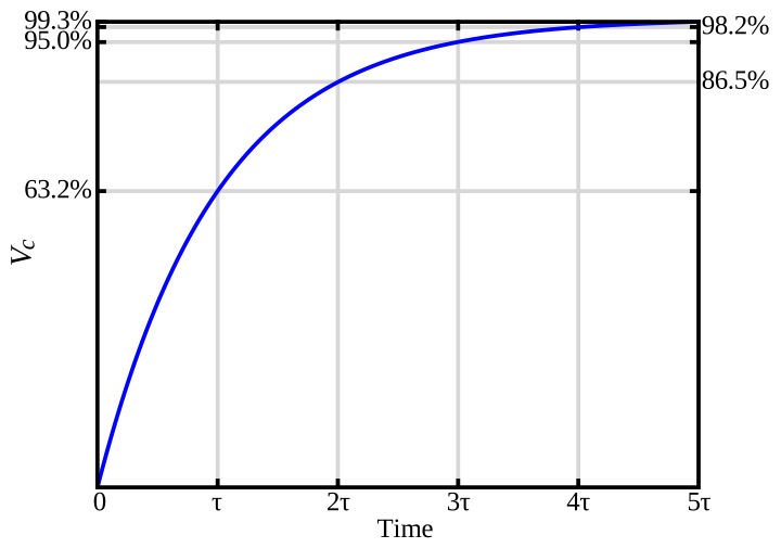
Charging curve. Voltage across the capacitor rises exponentially, reaching 63% of maximum after one time constant (τ=RC) and ~99% after five time constants. Current simultaneously decays from its maximum toward zero. Credit: Wikimedia Commons, CC BY-SA
During charging:
Charge Q(t) starts at 0 and grows exponentially toward Qmax=CVbattery.
Current I(t) starts at Imax=Vbattery/R and decays exponentially toward 0.
Capacitor voltage VC(t) starts at 0 and grows toward Vbattery.
Discharging an RC Circuit
When a fully charged capacitor is disconnected from the battery and connected through a resistor, the stored charge flows back out through the resistor. Current starts high (large V across the capacitor) and decays toward zero as the capacitor drains.
During discharging, all three quantities (Q, I, VC) start at their initial values and decay exponentially toward zero — same time constant.
The Time Constant
The time constant is just a number with units of seconds — and the percentages of completion at each multiple of τ are the same for every RC circuit:
Time elapsed
Charging (% of max)
Discharging (% remaining)
1 τ
63%
37%
2 τ
86%
14%
3 τ
95%
5%
5 τ
~99%
~1%
Why 63% and 37%?
These come from the exponential function. After one time constant, e−1≈0.37 (37%). For charging, the capacitor reaches 1−0.37=0.63 (63%) of its maximum. You don’t need to work with e on the MCAT — just memorize the 3763 split at 1 τ, and the “essentially done at 5 τ” rule.
How R and C Affect the Time Constant
Larger R → larger τ → slower charging/discharging (current is more restricted).
Larger C → larger τ → slower charging/discharging (more charge to move on/off the plates).
Smaller R or C → smaller τ → faster response.
Practical consequence: if you want a fast camera flash (rapid discharge), you use a small resistor and a moderate capacitor. If you want a slow circuit (a windshield-wiper delay), you use a big resistor.
Circuit Problem-Solving Strategy
Here’s a general game plan for any MCAT circuit problem:
Simplify. Identify resistors and capacitors that are in series or parallel. Combine them into equivalent values. Redraw the simplified circuit.
Apply the big rules. Ohm’s law (V=IR), Kirchhoff’s junction rule (current in = current out), Kirchhoff’s loop rule (voltage gains = voltage drops around any loop).
Identify what’s constant. In series: current is the same. In parallel: voltage is the same. For capacitors with battery connected: V is constant. For isolated capacitors: Q is constant.
Use the right power formula.P=IV, P=I2R, or P=V2/R — pick the one that matches the variables you already know.
Check your answer. Does total resistance look reasonable (parallel < smallest)? Do voltage drops sum to the EMF (KVL)? Do currents balance at junctions (KCL)?
A 2 kΩ resistor is in series with a 50 μF capacitor. What is the time constant? After how many seconds is the capacitor approximately 63% charged?
Click to reveal answer
τ=0.1 s.τ=RC=(2000)(50×10−6)=0.1 s. So 63% charged at 0.1 s, essentially fully charged at 0.5 s (5τ).
A fully charged capacitor begins discharging through a resistor. The time constant is 4 seconds. Approximately how much charge remains after 4 seconds? After 20 seconds?
Click to reveal answer
After 4 s (1τ): 37% remaining. After 20 s (5τ): ~1% — effectively fully discharged.
In an RC charging circuit, what is the *initial* current at t=0 (the instant the switch is closed)?
Click to reveal answer
I0=Vbattery/R. At t=0, the capacitor is uncharged (VC=0), so it acts like a *wire* (zero voltage drop across it). The full battery voltage is across the resistor → I=V/R. As charge builds, VC grows and current decays.