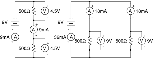
When resistors are lined up end-to-end so that all the current must pass through every one of them, they’re in series. This is the simplest circuit configuration and the first one to master — once you nail series, parallel and combinations become much easier to reason about.
The defining feature of series: there’s only one path for current to take. No branching, no shortcuts, no alternate routes.
The Series Rules
Series vs. parallel resistor configurations. In series, all current flows through every resistor (same current, voltages add). In parallel, current splits among branches (same voltage, currents add). Recognizing which configuration you’re dealing with is the first step in any circuit problem. Credit: Wikimedia Commons, CC BY-SA
Picture three narrow water-park slides connected one after another. All the water entering slide 1 must flow through slide 2 and then slide 3. None of it can take a shortcut. That’s the defining property of a series circuit:
The current is the same through every resistor in series.
Since the same current flows through every resistor, Ohm’s law tells us each resistor drops a voltage proportional to its resistance:
V1=IR1, V2=IR2, V3=IR3.
Those voltage drops have to add up to the total voltage supplied by the battery:
Vtotal=V1+V2+V3+…
This is conservation of energy: every coulomb of charge gets some energy from the battery, then “spends” it dropping through each resistor before returning to the battery.
The Voltage Divider
When the MCAT gives you a series circuit and asks for the voltage across one specific resistor, use the voltage divider formula:
Example. A 12 V battery is connected to a 2 Ω and a 4 Ω resistor in series. Rtotal=6 Ω.
Voltage across 4 Ω: 12×(4/6)=8 V.
Voltage across 2 Ω: 12×(2/6)=4 V.
Check: 8+4=12 V. ✓
The bigger resistor “hogs” more of the voltage drop, in direct proportion to its share of the total resistance.
Interactive Circuit Explorer
🎯 Predict First
Two resistors are in series with a battery. You double the resistance of the FIRST resistor. What happens to the current through the SECOND resistor?
Use this simulation to build series and parallel circuits. Adjust resistor values and battery voltage, then watch current flow and voltage distributions update in real time. Toggle between series and parallel to see how the same resistors behave completely differently.
Rtotal 30.00 ΩItotal 0.40 APtotal 4.80 W
R1 = 10 ΩV = 4.00 VI = 0.40 AP = 1.60 W
R2 = 20 ΩV = 8.00 VI = 0.40 AP = 3.20 W
Series: same current through all resistors; voltage divides proportional to R.
Series Circuit Summary
| Property | Series rule |
|----------|-------------------|
| Current | Same through all resistors |
| Voltage | Divides among resistors (V=IR for each) |
| Total resistance | Rtotal=R1+R2+… (sums up) |
| If one resistor breaks (open) | Entire circuit stops — no current anywhere |
Three resistors (3 Ω, 5 Ω, 2 Ω) are connected in series to a 20 V battery. What is the current in the circuit and the voltage across the 5 Ω resistor?
Click to reveal answer
I=2 A; V5Ω=10 V.Rtotal=3+5+2=10 Ω. I=V/R=20/10=2 A. Voltage across 5 Ω: V=IR=2×5=10 V. (Or by voltage divider: 20×(5/10)=10 V.)
Two resistors are in series. The voltage across the first is three times the voltage across the second. If R2=4 Ω, what is R1?
Click to reveal answer
R1=12 Ω. Same current through both, so V∝R. V1=3V2⇒R1=3R2=12 Ω.
Four identical 5 Ω resistors are connected in series to a 10 V battery. What is the current through each resistor?
Click to reveal answer
0.5 A through every resistor.Rtotal=4×5=20 Ω. I=V/R=10/20=0.5 A. Same current flows through all four — that’s the defining feature of series.