Your microwave heats leftovers. A radio tower broadcasts to your car. A hospital X-ray images your broken wrist. Your phone uses gigahertz signals to talk to a cell tower. The sun warms your face with infrared.
These look like completely different technologies — but they’re all the same thing: electromagnetic (EM) waves traveling at the speed of light. The only difference between a radio wave and a gamma ray is the wavelength.
That single fact is the punch of this section. Once you internalize that the entire electromagnetic spectrum is just one phenomenon at different wavelengths, the rest of optics — and a lot of biology, chemistry, and medical imaging — clicks into place.
What Are Electromagnetic Waves?
An EM wave is a pair of oscillating fields — one electric, one magnetic — that travel together through space at right angles to each other and to the direction of motion. Neither field needs a medium to oscillate in. Unlike sound (which requires air or water or some material), light can cross the vacuum of space — which is how sunlight reaches Earth across 93 million miles of nothing.
Key properties of all EM waves:
They are transverse waves (oscillation perpendicular to propagation).
The electric and magnetic fields are perpendicular to each other.
They travel at the speed of light in vacuum: c=3×10⁸ m/s.
They do not require a medium — they can travel through vacuum.
They carry energy and can transfer it to matter (think solar panels, X-ray exposure, sunburns).
The Fundamental Equation
This one equation tells you everything about the trade-off between frequency and wavelength. Double the frequency, halve the wavelength. Know one, you know the other.
The Spectrum: From Low Energy to High Energy
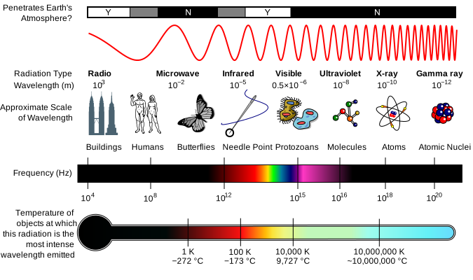
The electromagnetic spectrum. From radio waves (longest wavelength, lowest energy) to γ rays (shortest wavelength, highest energy). All EM waves travel at c in vacuum. The visible band is a tiny sliver of the full spectrum. Credit: Wikimedia Commons, CC BY-SA
The EM spectrum arranged from longest wavelength to shortest:
Region
Wavelength range
Frequency range
Common use
Radio
> 1 m
< 3×10⁸ Hz
AM/FM radio, TV, broadcast
Microwave
1 mm – 1 m
3×10⁸ – 3×10¹¹ Hz
Microwave ovens, cell phones, WiFi
Infrared (IR)
700 nm – 1 mm
up to 4.3×10¹⁴ Hz
Heat sensing, remote controls
Visible
400 – 700 nm
4.3×10¹⁴ – 7.5×10¹⁴ Hz
Human vision
Ultraviolet (UV)
10 – 400 nm
up to 3×10¹⁶ Hz
Sunburn, sterilization
X-ray
0.01 – 10 nm
up to 3×10¹⁹ Hz
Medical imaging
Gamma (γ)
< 0.01 nm
> 3×10¹⁹ Hz
Nuclear decay, cancer treatment
The Energy Relationship
Higher frequency → higher energy per photon. This determines how EM radiation interacts with matter:
Radio waves pass harmlessly through your body — too low-energy to break bonds.
Microwaves make water molecules rotate, generating heat (that’s how a microwave oven works).
Visible light excites electrons in retinal pigments → vision.
UV light can break chemical bonds in DNA → mutations and sunburn.
X-rays penetrate soft tissue but get absorbed by dense bone → medical imaging contrast.
Gamma rays can destroy cells → used in radiation therapy for tumors.
The reason UV is dangerous and visible light isn’t comes down to one fact: UV photons carry enough energy to break covalent bonds in DNA. Visible photons don’t. That’s why a sunburn happens from UV exposure even though visible light from the sun is way more intense — it’s about the energy per photon, not total energy delivered.
Speed of Light in Different Media
In vacuum, all EM waves travel at exactly c=3×10⁸ m/s. In a material medium (glass, water, air), light slows down. The amount it slows depends on the material’s index of refraction, covered in §8.4. For now:
Light is fastest in vacuum.
Light slows down in matter.
Frequency stays the same when light enters a new medium; wavelength changes (since v changes and f doesn’t).
A radio station broadcasts at 100 MHz. What is the wavelength of the signal?
Click to reveal answer
3 m.λ=c/f=(3×108)/(100×106)=3 m. Radio waves have long wavelengths — this one is about the length of a car. That's why radio antennas tend to be large.
Rank from lowest to highest energy per photon: visible light, γ rays, microwaves, X-rays.
Click to reveal answer
microwaves < visible < X-rays < γ rays. Energy increases with frequency. Microwaves have the lowest frequency of the four; γ rays have the highest. Use the "Raging Martians" mnemonic ordering.
Visible green light has a wavelength of 550 nm. What is its frequency?
Click to reveal answer
∼5.5×10¹⁴ Hz.f=c/λ=(3×108)/(550×10−9)≈5.5×1014 Hz. Visible light frequencies sit in the hundreds of trillions of Hz range — much higher than radio or microwave, much lower than UV/X-ray.
Light is weird. It does something no everyday object does — it behaves like a wave and a particle at the same time.
Shine light through two narrow slits and it produces an interference pattern, exactly like water waves overlapping in a pond (very wave-like). Shine the same light at a metal surface and it knocks individual electrons off the metal, one at a time, like a stream of bullets (very particle-like). Neither model alone explains everything light does — only the combined “wave-particle duality” picture does.
This is also where modern physics (Einstein’s photoelectric effect, quantum mechanics) was born. For the MCAT, you don’t need to resolve the philosophical paradox — you just need to know when to use each model.
Wave-Particle Duality
Light is both a wave and a stream of particles called photons. Which behavior you see depends on the experiment:
Wave behavior: interference, diffraction, polarization (covered in §§8.11–8.12).
Particle behavior: the photoelectric effect, Compton scattering, emission and absorption of light by atoms.
The MCAT-friendly rule of thumb: wave properties explain how light bends, interferes, and spreads. Particle properties explain how light transfers energy to matter.
Photon Energy
Each photon carries a specific amount of energy determined by its frequency:
This equation is the bridge between the wave model and the particle model. Frequency (a wave property) determines the energy of each photon (a particle property).
The Visible Spectrum
Visible light is the narrow band of the EM spectrum that human eyes can detect — about 400 nm (violet) to 700 nm (red).
Color
Approximate wavelength
Relative energy
Red
~700 nm
Lowest
Orange
~620 nm
Yellow
~580 nm
Green
~530 nm
Blue
~470 nm
Violet
~400 nm
Highest
Color Perception
When white light (which contains all visible wavelengths) hits an object, some wavelengths get absorbed and others get reflected. The reflected wavelengths are what your eyes detect as color:
A red apple absorbs most wavelengths and reflects red (~700 nm).
A white shirt reflects all visible wavelengths.
A black shirt absorbs all visible wavelengths (which is why black surfaces get hotter in the sun).
This is subtractive color — the object subtracts certain wavelengths and you see what remains. Screens and projectors use additive color, combining red, green, and blue light to create the full color range your eye can perceive. (RGB on a screen vs. CMYK in a printer is exactly this distinction.)
Intensity vs. Photon Energy
Two properties of a light beam that students often confuse — and the MCAT loves the confusion:
Intensity (brightness) depends on the number of photons per second hitting a surface.
Photon energy depends on the frequency of each individual photon.
Turning up the brightness of a red laser pours out more red photons per second but doesn’t change the energy of each one. Switching from a red laser to a blue laser increases the energy per photon but says nothing about total brightness.
This distinction matters in biology too: UV light damages DNA not because it’s bright, but because each individual UV photon has enough energy to break a covalent bond. Bright red light might pour vastly more total energy onto your skin without causing any damage, because no single red photon is energetic enough to break a bond.
A photon has wavelength 500 nm. If the wavelength is halved to 250 nm, what happens to its energy?
Click to reveal answer
Energy doubles.E=hc/λ, so energy is inversely proportional to wavelength. Halving λ doubles E. The 250 nm photon (UV range) carries twice the energy of the 500 nm photon (green visible).
A red laser and a violet laser each emit 1000 photons per second. Which beam delivers more total energy per second?
Click to reveal answer
The violet laser. Violet has higher frequency than red, so each violet photon carries more energy (E=hf). With equal numbers of photons per second, the beam with higher-energy photons delivers more total energy.
Why doesn't visible light damage DNA the way UV light does, even when the visible light is brighter?
Click to reveal answer
Because each individual visible photon doesn't carry enough energy to break a covalent bond. DNA damage requires breaking bonds, which is done one photon at a time. Visible photons (~2 eV each) are below the bond-breaking threshold; UV photons (~3–10 eV) clear it. Brightness only adds more photons; it doesn't increase the energy *per* photon.
You look into a still lake and see the mountains reflected perfectly. You look at the rough pavement next to it and see no reflection at all — even though the same sunlight is hitting both surfaces.
The difference isn’t whether light reflects (it always does, off basically everything you can see). The difference is whether the surface is smooth enough to keep the reflected rays organized into a coherent image.
That distinction — between specular reflection (mirrors, calm water) and diffuse reflection (paper, wood, your skin) — is what determines whether you see a clean image or just a dimly lit object.
The Law of Reflection
When light hits a surface, the angle at which it arrives equals the angle at which it bounces off. Both angles are measured from the normal — an imaginary line perpendicular to the surface at the point of contact.
Specular vs. Diffuse Reflection
Specular reflection happens on smooth surfaces (mirrors, calm water, polished metal). All incoming parallel rays reflect in the same direction, preserving the image.
Diffuse reflection happens on rough surfaces (paper, unpolished wood, concrete). The surface has microscopic bumps, so each ray hits a slightly different normal. Reflected rays scatter in all directions. You can still see the object (diffuse reflection is how you see most things — paper, walls, skin), but you don’t see a mirror image.
Both types obey the law of reflection at each individual point. The difference is just whether the surface is smooth enough at the scale of the wavelength of light for all the local normals to point in the same direction. A piece of paper looks “smooth” to your eye but has surface roughness comparable to or larger than 500 nm (visible-light wavelength), so each tiny patch reflects in a different direction → diffuse.
Plane Mirrors
A plane mirror is a flat reflective surface. It produces images with very predictable properties:
The image is virtual (light rays don’t actually converge behind the mirror).
The image is upright (same orientation as the object).
The image is the same size as the object (magnification = 1).
The image distance equals the object distance: di=do (behind the mirror).
The image is laterally inverted (left and right are swapped — which is why a written word in the mirror reads “backward”).
Why Virtual?
A real image forms where light rays actually converge — you could place a screen there and see the image projected onto it. A virtual image forms where light rays only appear to come from when your brain traces them backward.
In a plane mirror, reflected rays diverge (spread apart) after bouncing off the surface. Your eye traces them back along straight lines to a point behind the mirror. No light actually passes through that point. The image is virtual.
This distinction between real and virtual becomes critical in the mirror and lens sections coming up. Get it locked in now and the rest of the chapter will be much easier.
You stand 2 m in front of a plane mirror. How far away does your image appear to be from you?
Click to reveal answer
4 m. The image is 2 m behind the mirror (di=do=2 m). You are 2 m in front. Total distance you-to-image: 2+2=4 m.
Light strikes a flat mirror at 25° to the *surface*. What is the angle of reflection (from the normal)?
Click to reveal answer
65°. Angle to the surface = 25°, so angle from the normal = 90−25=65°. By the law of reflection, θr=θi=65°.
Why can you see your reflection in a still pond but not in choppy water?
Click to reveal answer
Still water = specular reflection (smooth surface, organized rays). Choppy water = diffuse reflection (rough surface, scattered rays). The law of reflection holds at every point in both cases — but in choppy water, the local "normals" point in many different directions, so reflected rays scatter and no coherent image forms.
Stick a straw in a glass of water and look at it from the side. The straw appears to bend or break sharply at the water’s surface. Your eyes aren’t lying, and the straw isn’t actually broken — but the image of the underwater portion is in the wrong place.
Light traveling from the underwater part of the straw changes direction when it crosses from water into air. Your brain traces those bent rays backward in a straight line, so it perceives the underwater straw shifted from where it actually is. That bending of light at a boundary is refraction — and it’s the principle that makes lenses (and your eyes) able to form images.
Index of Refraction
Every transparent material slows light down by a characteristic amount. The index of refraction (n) tells you how much:
| Material | Index of refraction (n) |
|----------|------------------------|
| Vacuum | 1.00 (exact) |
| Air | 1.00 (effectively) |
| Water | 1.33 |
| Glass (typical) | 1.50 |
| Diamond | 2.42 |
What Causes Refraction?
When a light wave crosses from one medium into another, its speed changes but its frequency stays the same (frequency is locked in by the source — same rule from §7.1). Since v=fλ, if speed decreases and frequency is fixed, wavelength must shrink too. The change in speed at the boundary causes the wavefront to pivot, bending the light ray.
Snell’s Law
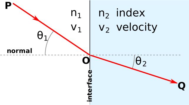
Snell’s law in action. A light ray bends toward the normal when entering a denser medium (higher n), and away from the normal when entering a less dense medium. Angles and indices linked by n1sinθ1=n2sinθ2. Credit: Wikimedia Commons, CC BY-SA
Snell’s law is the quantitative rule for refraction. Plug in three of the four quantities and solve for the fourth.
The Two Bending Rules
You can predict the direction of bending without doing any math:
Entering a denser medium (n increases): light bends toward the normal. Angle gets smaller. (“Light slows down and turns in.”)
Entering a less dense medium (n decreases): light bends away from the normal. Angle gets larger. (“Light speeds up and turns out.”)
🎯 Predict First
Light passes from water (n = 1.33) into air (n = 1.00). As you keep increasing the angle of incidence, what eventually happens?
Test your prediction with the simulation below. Make n1 larger than n2, then drag the incident angle upward and watch the refracted ray swing away from the normal while the faint reflected ray grows stronger. Push the incident ray past the dashed critical angle marker and see where the light goes.
θ₁: 40°θ₂: 60.2°Critical angle: 47.8°Bend: away from the normal
Important Details
Light hitting the boundary at θ=0 (perpendicular) doesn’t bend. Snell’s law confirms: n1sin0=0=n2sinθ2⇒θ2=0.
Frequency stays constant when light enters a new medium. Speed and wavelength change together (both decrease in a denser medium); frequency is locked in by the source.
The path is reversible. If light bends 30° going from air into glass, it bends 30° the other way going from glass back into air along the same line.
Worked Example
Light travels from air (n=1.00) into water (n=1.33) at an angle of incidence of 45°. Find the angle of refraction.
n1sinθ1=n2sinθ2
(1.00)(sin45°)=(1.33)(sinθ2)
sinθ2=0.707/1.33≈0.532
θ2≈32°
Light bends toward the normal entering water (denser medium) — angle drops from 45° to 32°, exactly as the rule predicts.
Light goes from glass (n=1.50) into air (n=1.00) at an angle of incidence of 30°. What’s the angle of refraction? Does it bend toward or away from the normal?
Click to reveal answer
~48.6°, bending away from the normal.(1.50)(sin30°)=(1.00)(sinθ2)⇒sinθ2=0.75⇒θ2≈48.6°. Going to a less dense medium (lower n) → bends away from normal → larger angle.
Light has wavelength 600 nm in vacuum. What’s its wavelength in glass (n=1.50)?
Click to reveal answer
400 nm. In a medium with index n: λmedium=λvacuum/n=600/1.50=400 nm. Frequency unchanged, but wavelength shrinks because the light slows down.
A diver underwater shines a flashlight straight up at the surface (θ=0). What happens to the beam as it crosses into air?
Click to reveal answer
It passes straight through with no bending. Light hitting a boundary perpendicular to the surface (θ1=0) doesn’t refract — Snell’s law gives sin0=0, so θ2=0 regardless of the indices. Refraction only happens at non-zero angles.
A diamond sparkles with an almost supernatural brilliance. Light enters the gem — but instead of just passing through, it bounces around inside, reflecting off the internal facets multiple times before finally escaping out the top.
The diamond essentially traps light. The phenomenon is called total internal reflection (TIR), and it only happens under very specific conditions. It’s also the trick behind fiber-optic cables (which carry the entire global internet) and medical endoscopes (which let doctors see inside the body without cutting it open).
When Does Total Internal Reflection Occur?
TIR happens when two conditions are both met:
Light is traveling from a higher-n medium to a lower-n medium (denser → less dense).
The angle of incidence is greater than the critical angle.
If either condition fails, TIR doesn’t happen. Light going from air into glass (low → high) can never undergo TIR, no matter the angle.
The Critical Angle
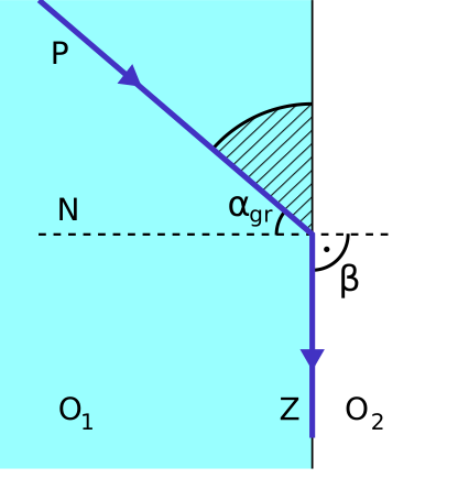
Total internal reflection. Below the critical angle: light refracts through. At the critical angle: refracted ray grazes the surface at 90°. Above the critical angle: all light reflects back into the denser medium. Credit: Wikimedia Commons, CC BY-SA
The critical angle (θc) is the angle of incidence at which the refracted ray just barely skims along the boundary surface (θ2=90°). Above this angle of incidence, no light is transmitted — all of it reflects.
This formula falls right out of Snell’s law with θ2=90°:
n1sinθc=n2sin90°=n2⇒sinθc=n2/n1.
Why the Ratio Matters
A small critical angle means light gets trapped easily — even at modest angles, TIR kicks in. A large critical angle means light can escape across most angles and only gets trapped at very steep approaches.
Interface
n1
n2
Critical angle
Glass → Air
1.50
1.00
41.8°
Water → Air
1.33
1.00
48.8°
Diamond → Air
2.42
1.00
24.4°
Fiber Optics
Fiber optic cables are arguably the most important application of TIR. A thin glass or plastic fiber (the core) is surrounded by a coating (cladding) with a lower refractive index. Light enters one end of the fiber and hits the core-cladding boundary at a steep angle — well above the critical angle. The light bounces along the length of the fiber via TIR, never escaping, even around gentle curves.
This is how the modern internet is built — undersea fiber-optic cables carry data at near light-speed across oceans. It’s also how endoscopes let doctors see inside organs (bundles of fibers carry images out from the body), and how a laparoscopic surgeon can operate through tiny incisions.
What Happens at Each Angle?
θ<θc: Most light refracts through (some reflects). Normal refraction.
θ=θc: Refracted ray grazes the surface at 90°. The boundary case.
θ>θc: All light reflects back into the original medium. Zero transmission. TIR.
Calculate the critical angle for light traveling from glass (n=1.50) into water (n=1.33).
Click to reveal answer
~62.5°.sinθc=n2/n1=1.33/1.50≈0.887⇒θc≈62.5°. Since n1>n2 (glass is denser than water), TIR is possible. Any angle of incidence > 62.5° → all light reflects back into the glass.
Can TIR occur when light travels from air (n=1.00) into diamond (n=2.42)? Why or why not?
Click to reveal answer
No. TIR only happens when going from higher n to lower n. Air (n=1) is *less* dense than diamond (n=2.42), so this is a low-to-high transition. Light going from air into diamond always partially transmits — TIR is impossible at this interface.
Why can a fiber-optic cable transmit light around gentle curves without losing signal?
Click to reveal answer
Because every reflection inside the fiber is a total internal reflection. The core has higher n than the cladding, and light hits the boundary at angles steeper than the critical angle. So 100% of the light reflects back into the core every time — no transmission losses, no leakage. Even with curves, as long as the angle stays above θc, TIR keeps the light bouncing forward.
Shine a narrow beam of white light through a glass prism and a rainbow fans out the other side. Isaac Newton first did this experiment in the 1660s and proved something that surprised everyone: white light isn’t a single color — it’s a mixture of every visible wavelength traveling together.
The prism doesn’t add color to the light. It reveals what was already there by bending each wavelength by a slightly different amount. That phenomenon is dispersion, and it explains rainbows, prisms, the colors at the edges of cheap binoculars, and a class of lens problems called chromatic aberration.
Why Dispersion Happens
The index of refraction of a material isn’t a single fixed number — it depends slightly on the wavelength of light passing through. Shorter wavelengths (violet, blue) experience a higher index than longer wavelengths (red, orange).
Since higher n means light slows down more and bends more, violet bends the most and red bends the least when going through a prism.
Prisms
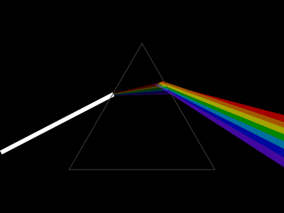
Dispersion through a prism. Each wavelength has a slightly different index in glass, so each color refracts by a slightly different angle. Violet bends the most; red bends the least. Credit: Wikimedia Commons, CC BY-SA
When white light enters a prism, each wavelength refracts by a slightly different angle. The small differences add up — especially because the light refracts twice (once entering the prism, once exiting). The exit beam is the visible spectrum spread out in order: red, orange, yellow, green, blue, violet.
Rainbows
Rainbows are dispersion in the wild. Sunlight enters a spherical raindrop, refracts at the front surface (slightly separating the colors), reflects off the back surface, and refracts again on the way out. The two refractions amplify the color separation. Each color exits the raindrop at a slightly different angle — red exits at ~42° from the anti-solar point, violet at ~40°. That’s why you see red on the outside of the rainbow arc and violet on the inside.
White light passes through a glass prism. Which color is refracted the most? Which the least?
Click to reveal answer
Violet most; red least. Violet has the shortest visible wavelength → highest n in glass → most bending. Red has the longest wavelength → lowest n → least bending.
In a rainbow, why is red on the outside (top) of the arc and violet on the inside (bottom)?
Click to reveal answer
Because dispersion in raindrops bends violet more than red. Sunlight enters each raindrop and is refracted/reflected/refracted before exiting at different angles per color. Red emerges at ~42° from the antisolar point; violet at ~40°. Geometrically that puts red on the outside (larger angle) and violet on the inside (smaller angle).
Look at yourself in the back of a metal spoon. Hold the spoon close on the concave (bowl) side: your face appears magnified and right-side-up. Move it farther away and your image suddenly flips upside down. Now flip the spoon to the convex (back) side: your face is small and upright at every distance.
These aren’t optical illusions — they’re the predictable behavior of curved mirrors. One equation governs them all. Once you know the mirror equation, the sign conventions, and the qualitative behavior of concave vs. convex, every mirror problem on the MCAT becomes mechanical.
Concave vs. Convex Mirrors
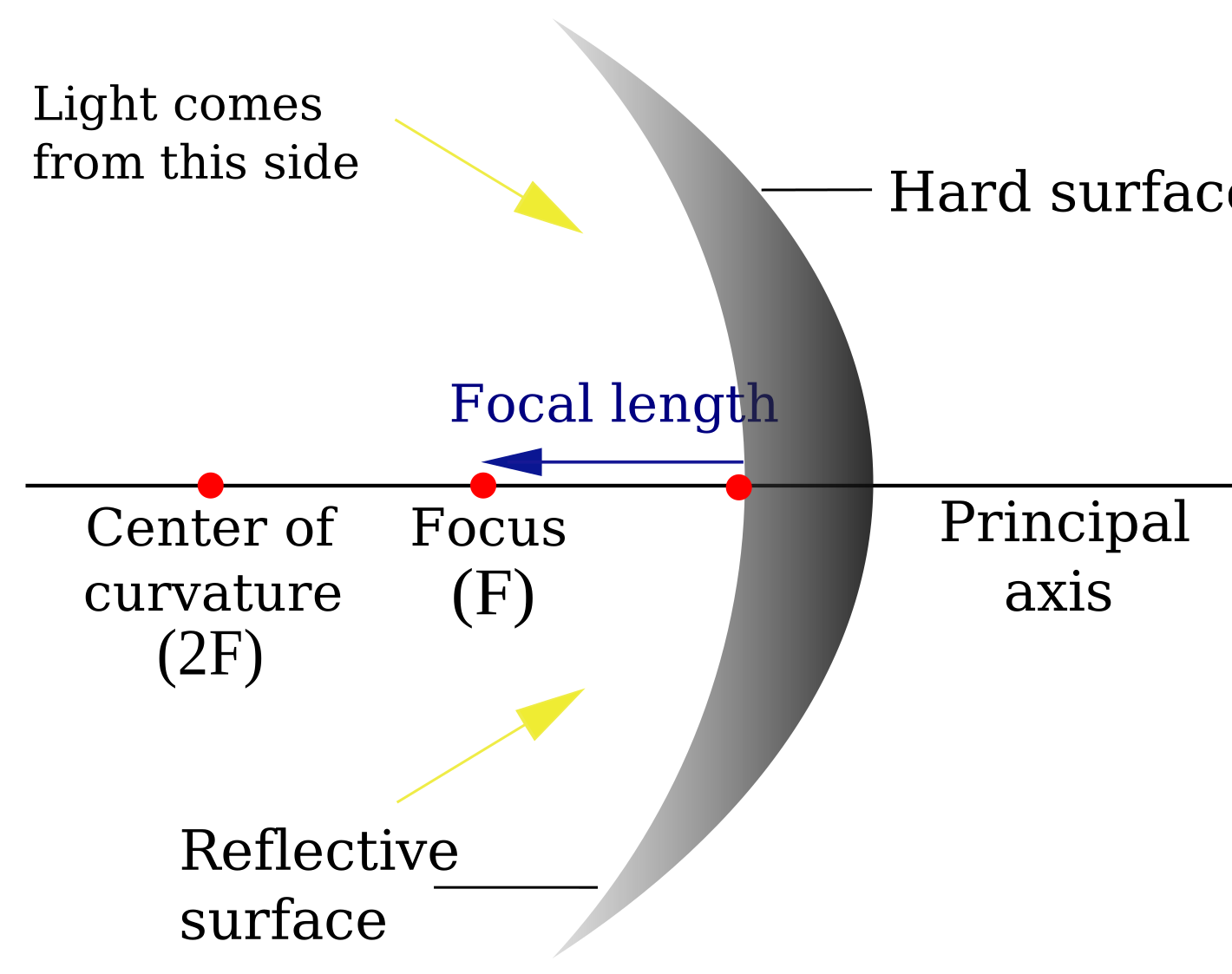
Concave mirrors curve inward (like the inside of a bowl). Parallel rays converge to a focal point in front of the mirror. They converge light → positive focal length (f>0).
Convex mirrors curve outward (like the back of a spoon). Parallel rays diverge as if from a focal point behind the mirror. They diverge light → negative focal length (f<0).
The Mirror Equation
Sign Conventions for Mirrors
Quantity
Positive (+)
Negative (−)
do
Object in front of mirror (real)
Object behind mirror (virtual — rare)
di
Image in front of mirror (real)
Image behind mirror (virtual)
f
Concave (converging)
Convex (diverging)
m
Upright
Inverted
Concave Mirror Image Cases
Ray diagram for a concave mirror. Parallel rays converge at the focal point (f). Image location, orientation, and size all depend on where the object sits relative to f and the center of curvature (C=2f). Credit: Wikimedia Commons, CC BY-SA
Object position
Image location
Image type
Orientation
Size
Beyond C (do>2f)
Between f and C
Real
Inverted
Reduced
At C (do=2f)
At C
Real
Inverted
Same size
Between C and f
Beyond C
Real
Inverted
Enlarged
At f (do=f)
At infinity
—
—
—
Inside f (do<f)
Behind mirror
Virtual
Upright
Enlarged
Convex Mirror Images
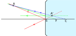
Ray diagram for a convex mirror. Reflected rays diverge, but tracing them backward reveals a virtual focal point behind the mirror. The image is always virtual, upright, and reduced. Credit: Wikimedia Commons, CC BY-SA
Convex mirrors are blissfully simple. No matter where you put the object, the image is always:
Virtual (behind the mirror, di negative).
Upright (m positive).
Reduced (∣m∣<1).
This is why convex mirrors are used as car side mirrors and store security mirrors — they always give an upright, reduced image with a wide field of view. The trade-off: objects look farther away than they really are. Hence the warning printed on every convex car mirror: “objects in mirror are closer than they appear.”
Ray Diagram Rules (Concave Mirror)
The mirror equation is faster, but ray diagrams build intuition. For a concave mirror, three reliable rays:
A ray parallel to the principal axis reflects through the focal point.
A ray through the focal point reflects parallel to the principal axis.
A ray through the center of curvature (C) reflects back on itself.
The intersection of any two of these rays is where the image forms. For convex mirrors, trace the reflected rays backward (behind the mirror) to find where they appear to intersect — that’s the virtual image location.
An object is placed 30 cm in front of a concave mirror with f=20 cm. Where is the image? Real or virtual? Upright or inverted?
Click to reveal answer
di=+60 cm; real and inverted.1/f=1/do+1/di⇒1/20=1/30+1/di⇒1/di=1/60⇒di=+60 cm. Positive di → real, in front of mirror. m=−60/30=−2 → inverted, 2× enlarged.
An object is placed 10 cm in front of a convex mirror with f=−20 cm. Where is the image? Describe it.
Click to reveal answer
di≈−6.7 cm; virtual, upright, reduced.1/(−20)=1/10+1/di⇒1/di=−1/20−1/10=−3/20⇒di≈−6.67 cm. Negative di → virtual (behind mirror). m=−(−6.67)/10≈+0.67 → upright, about 32 the original size.
Why does the warning "objects in mirror are closer than they appear" appear on convex car mirrors but not on flat mirrors?
Click to reveal answer
Because convex mirrors produce reduced images that look small (and therefore far away) even when the object is close. Flat mirrors produce 1:1 size images at the same apparent distance. Convex mirrors trade accurate size/distance for a wider field of view. The visual cue "smaller = farther" tricks your brain into thinking the trailing car is more distant than it really is.
Hold a magnifying glass over a piece of paper in sunlight. Tilt it until the sunlight converges to a tiny, brilliant point. That point is the focal point of the lens — and it’s hot enough to ignite the paper.
The magnifying glass is a converging lens. The thin-lens equation that governs it is identical to the mirror equation from §8.7. Learn one, and you’ve learned both. The whole job of this section is teaching you to use that equation, the sign conventions, and the qualitative image rules.
Converging vs. Diverging Lenses
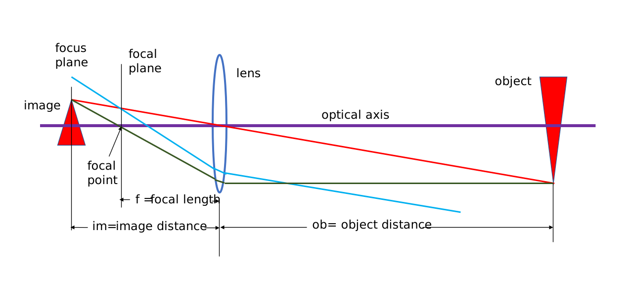
Converging lenses (convex — thicker in the middle) bring parallel light rays together to a focal point on the far side. Positive focal length (f>0).
Diverging lenses (concave — thinner in the middle) spread parallel light rays apart, as if from a focal point on the near side. Negative focal length (f<0).
The Thin Lens Equation
Sign Conventions for Lenses
| Quantity | Positive (+) | Negative (−) |
|----------|-------------|-------------|
| do | Object on incoming-light side | Object on outgoing-light side (rare) |
| di | Image on outgoing-light side (real) | Image on incoming-light side (virtual) |
| f | Converging (convex) | Diverging (concave) |
| m | Upright | Inverted |
Interactive Lens Simulator
🎯 Predict First
An object sits far from a converging lens, forming a real, inverted image. You slide the object inward until it is closer to the lens than the focal point. What happens to the image?
Drag the object arrow to see how image position, size, and orientation change with object distance. Switch between converging and diverging lenses. Watch the three principal rays trace image formation in real time. Pay close attention to what happens as the object crosses the focal point.
do30.0 cm
di30.0 cm
m-1.00×
ImageReal
OrientationInverted
Power6.67 D
Converging Lens Image Cases
Ray diagram for a converging (convex) lens. Three principal rays locate the image: parallel ray refracts through the far focal point; ray through the center passes straight; ray through the near focal point exits parallel. The intersection is the real image. Credit: Wikimedia Commons, CC BY-SA
Like concave mirrors, converging lenses produce different images depending on where the object sits:
| Object position | Image location | Image type | Orientation | Size |
|----------------|---------------|------------|-------------|------|
| Beyond 2f | Between f and 2f (far side) | Real | Inverted | Reduced |
| At 2f | At 2f (far side) | Real | Inverted | Same size |
| Between 2f and f | Beyond 2f (far side) | Real | Inverted | Enlarged |
| At f | At infinity | — | — | — |
| Inside f | Same side as object | Virtual | Upright | Enlarged |
Diverging Lens Images
Like convex mirrors, diverging lenses always produce the same type of image regardless of object position:
Virtual (same side as object, di negative).
Upright (m positive).
Reduced (∣m∣<1).
Diverging lenses by themselves never form real images.
Lens Power in Diopters
Optometrists don’t describe eyeglass lenses by focal length — they use diopters.
The advantage of diopters: lens powers add simply when lenses are placed in contact. Two lenses with powers P1 and P2 have combined power P1+P2. This is much easier than trying to combine focal lengths directly (which involves the reciprocal mess).
An object is placed 15 cm from a converging lens with f=10 cm. Where does the image form? Describe it.
Click to reveal answer
di=+30 cm; real, inverted, enlarged.1/10=1/15+1/di⇒1/di=1/30⇒di=+30 cm. Positive → real image on far side. m=−30/15=−2 → inverted, 2× enlarged.
A diverging lens has f=−25 cm. What is its power in diopters?
Click to reveal answer
P=−4 D. Convert f to meters: f=−0.25 m. P=1/f=−4 D. Negative confirms it’s a diverging lens.
Two thin lenses in contact have powers +2 D and −5 D. What is the combined focal length?
Click to reveal answer
f≈−33 cm (diverging). Powers add: Ptotal=+2+(−5)=−3 D. Then f=1/P=1/(−3)≈−0.33 m = −33 cm. The combination acts as a diverging lens (negative net power).
A single lens can magnify a few times. But the microscopes and telescopes that revolutionized science use two or more lenses working together, achieving magnifications no single lens could deliver. The principle is simple and elegant: the image produced by the first lens becomes the object for the second lens. Chain enough lenses together and you can image bacteria, atoms, or distant galaxies.
This section also covers the two big imperfections of real lenses (called aberrations) and how lens designers correct for them. Both topics are AAMC content-list items.
Two-Lens Systems
The recipe for any two-lens problem is short:
Ignore the second lens for now. Use the thin-lens equation with lens 1 to find di1 and m1.
The image from lens 1 becomes the object for lens 2. Object distance for lens 2: do2=(lens separation)−di1.
Apply the thin-lens equation again to lens 2 to find di2 and m2.
Total magnification:mtotal=m1×m2.
A Worked Example
Two converging lenses are 30 cm apart. Lens 1 has f1=10 cm, Lens 2 has f2=15 cm. Object is 20 cm in front of Lens 1.
Step 1 — Lens 1.1/10=1/20+1/di1⇒di1=20 cm. m1=−20/20=−1. Image: 20 cm behind lens 1, real, inverted, same size.
Step 2 — Object for Lens 2. Image from lens 1 is 20 cm behind lens 1; the lenses are 30 cm apart, so the image sits 10 cm in front of lens 2 → do2=10 cm.
Step 3 — Lens 2.1/15=1/10+1/di2⇒1/di2=1/15−1/10=−1/30⇒di2=−30 cm. m2=−(−30)/10=+3. Image: virtual (di2<0), upright relative to its object, 3× magnified.
Step 4 — Total.mtotal=(−1)(+3)=−3. Final image is inverted relative to the original object and 3× its size.
Lenses in Contact
When two thin lenses are placed directly against each other (separation = 0), you can skip the multi-step process. Their powers in diopters simply add:
Chromatic Aberration
Real lenses suffer from imperfections called aberrations. The first one: chromatic aberration, caused by dispersion (§8.6). The index of refraction depends on wavelength, so different colors focus at slightly different points.
Violet light (higher n) bends more → focuses closer to the lens.
Red light (lower n) bends less → focuses farther from the lens.
The result: colored halos or fringes around the edges of an image, especially near contrast boundaries.
Correction: an achromatic doublet pairs a converging lens (made of “crown glass”) with a diverging lens (made of “flint glass”) of different dispersive properties. The two lenses’ chromatic effects largely cancel, producing a much sharper image. This is what’s inside high-quality cameras, microscopes, and telescopes.
Spherical Aberration
The second imperfection: spherical aberration. The outer edges of a spherical lens (or mirror) focus light at a shorter distance than the center. Rays hitting near the rim converge sooner than rays hitting near the optical axis. The result: a fuzzy image rather than a sharp one.
Correction: Use a lens with a non-spherical (aspheric) surface — engineering perfection but expensive. Or place an aperture (a small opening) in front of the lens to block the problematic outer rays. Cameras do this every time you “stop down” the aperture (smaller f-number) for a sharper image.
A converging lens (f=+20 cm) and a diverging lens (f=−30 cm) are placed in contact. What is the combined focal length?
Click to reveal answer
ftotal=+60 cm.1/ftotal=1/20+1/(−30)=3/60−2/60=1/60⇒ftotal=60 cm. Positive → combination is converging. (In diopters: 5+(−3.33)=+1.67 D.)
Which type of aberration causes colored fringes around the edges of an image? What causes it?
Click to reveal answer
Chromatic aberration, caused by dispersion. The index of refraction varies with wavelength, so different colors focus at different distances. Violet focuses closest (highest n, bends most); red focuses farthest. The mismatch creates colored fringes near edges. Fixed with an achromatic doublet.
A camera operator "stops down" the aperture (uses a smaller opening). Why does this reduce spherical aberration?
Click to reveal answer
It blocks the outer rays that focus at a different distance than the center rays. Spherical aberration arises because outer (rim) rays focus sooner than central (axial) rays. A smaller aperture limits light to the *central* region of the lens, where focusing is more uniform. Trade-off: less light reaches the sensor, so you need a longer exposure or higher ISO.
Your eye is the most sophisticated optical instrument you’ll ever use. It has a converging lens system that automatically adjusts its focal length, a self-regulating aperture, and a detector (the retina) packed with over 100 million light-sensitive cells.
Understanding how the eye focuses light — and what goes wrong in myopia, hyperopia, and astigmatism — is high-yield MCAT material that ties together everything from the previous sections (refraction, lens equation, diopters) into a single biological system.
Anatomy of the Eye as an Optical System
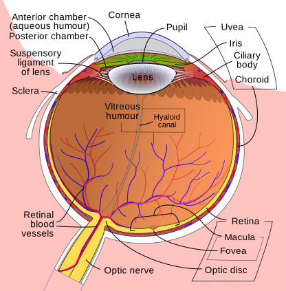
The human eye as an optical system. Light is refracted first by the cornea (about 32 of focusing power) and then fine-tuned by the adjustable lens. The iris controls light intake; the image forms on the retina at the back. Credit: Wikimedia Commons, CC BY-SA
Light entering the eye is refracted by two main structures:
Cornea — the transparent front surface. It provides about two-thirds of the eye’s total refractive power, because of the huge change in index of refraction between air (n=1.00) and the cornea (n=1.38).
Lens — the adjustable internal lens. It provides the remaining one-third of refractive power and can change shape to fine-tune focus.
After passing through both structures, light converges to form a real, inverted image on the retina at the back of the eye. Your brain flips the inverted image to “right-side up” automatically — you’ve never seen the world upside down because your visual cortex compensates.
Accommodation
Accommodation is the process by which the lens changes shape to focus on objects at different distances:
Near objects: ciliary muscles contract → lens becomes rounder → focal length decreases. More bending needed to converge the diverging rays from a close object.
The near point is the closest distance the eye can focus clearly (~25 cm in a young adult). The far point is the farthest (infinity for a normal eye).
Myopia (Nearsightedness)
A myopic eye sees nearby objects clearly but distant objects look blurry.
Cause: The eyeball is too long front-to-back, or the cornea/lens is too strong. Either way, light from distant objects converges to a focal point in front of the retina, then diverges again before reaching the retina.
Correction: A diverging (concave) lens with negative power. The lens spreads incoming rays slightly before they reach the eye, pushing the focal point back onto the retina.
Hyperopia (Farsightedness)
A hyperopic eye sees distant objects clearly but near objects look blurry.
Cause: Eyeball is too short, or the cornea/lens is too weak. Light from near objects would converge behind the retina if the system extended that far.
Correction: A converging (convex) lens with positive power. The lens adds extra convergence, bringing the focal point forward onto the retina.
Condition
Eye shape
Problem
Corrective lens
Sign
Myopia
Too long
Distant blur
Diverging (concave)
Negative (−)
Hyperopia
Too short
Near blur
Converging (convex)
Positive (+)
Microscopes and Telescopes
Astigmatism
Astigmatism happens when the cornea (or lens) isn’t perfectly spherical — it curves more in one direction than the other (think the back of a spoon vs. a perfect ball). Light then focuses at different distances depending on the orientation, producing blurred or distorted images. Corrected with cylindrical lenses that compensate for the uneven curvature in just the right axis.
A patient has a prescription of $-2.5$ D. Is the patient myopic or hyperopic? What type of lens is in the glasses?
Click to reveal answer
Myopic (nearsighted); diverging (concave) lens. Negative diopters → diverging lens → corrects myopia. Focal length: f=1/P=−0.40 m = −40 cm.
Which structure of the eye provides the most refractive power — the cornea or the lens? Why?
Click to reveal answer
The cornea (~32 of the total refractive power). The cornea-air interface has a *huge* index change (n goes from 1.00 to 1.38), so light bends a lot there. The internal lens is surrounded by aqueous and vitreous humor with n values close to its own — much smaller index change → less bending. The cornea does most of the heavy focusing; the lens just fine-tunes it via accommodation.
Why do most people need reading glasses around age 45?
Click to reveal answer
Presbyopia: the lens stiffens with age and loses its ability to accommodate (round up) for close objects. The eyeball shape doesn't change — only the lens elasticity. Reading glasses are converging lenses that supply the extra refraction the lens can no longer provide on its own. Often a +1.0 to +3.0 D add-on, depending on severity.
Drop two pebbles into a still pond at the same time. Where the expanding ripples overlap, you see something curious: some spots have extra-tall waves (the crests added together), while other spots are eerily flat (a crest met a trough and they canceled).
That’s interference. Light does the exact same thing — and the patterns it produces (bright and dark bands, the rainbow colors of soap bubbles, X-ray diffraction images of DNA) are some of the strongest evidence we have that light behaves as a wave. The MCAT tests interference in three flavors: double-slit, thin films, and diffraction gratings/single slits.
Constructive and Destructive Interference
Constructive interference: two waves arrive in phase (crest meets crest). Amplitudes add → bright spot. Path difference: 0, λ, 2λ, 3λ, … (whole number of wavelengths).
Destructive interference: two waves arrive out of phase (crest meets trough). Amplitudes cancel → dark spot. Path difference: λ/2, 3λ/2, 5λ/2, … (half a wavelength off — half, one-and-a-half, two-and-a-half wavelengths, and so on).
Young’s Double-Slit Experiment
Young's double-slit pattern. Coherent light diffracts through two narrow slits, the wavefronts overlap on a screen, and the result is alternating bright (constructive) and dark (destructive) fringes. Credit: Wikimedia Commons, CC BY-SA
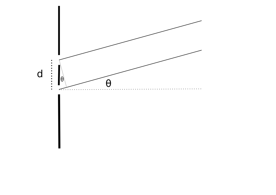
Thomas Young’s 1801 experiment is the classic demonstration of light’s wave nature. Coherent light passes through two narrow slits separated by distance d. The light from each slit spreads out (diffracts), and the two expanding wavefronts overlap on a distant screen — producing alternating bright and dark bands.
Three relationships to lock in:
Longer wavelength → wider spacing between fringes (red light produces wider bands than blue).
Smaller slit separation d → wider spacing between fringes.
Larger distance to screen → wider fringes (pattern fans out).
Thin Film Interference
When light hits a thin transparent film (soap bubble, oil slick on water, anti-reflective coating on glasses), some reflects off the top surface and some off the bottom. Those two reflected beams interfere with each other, producing the shimmering colors you see.
Two factors determine whether the interference is constructive or destructive:
Path difference. The beam reflecting off the bottom travels an extra distance of 2t (down and back up through a film of thickness t).
Phase shift on reflection. When light reflects off a surface with higher index, it picks up a 180° phase shift (= half a wavelength). Off a lower index surface, no phase shift.
The wavelength inside the film is shorter: λfilm=λvacuum/nfilm. Use this wavelength when calculating path differences.
Case 1 — One phase shift (most common: air → film → glass, where nfilm>nair):
Constructive: 2t=(m+21)λfilm.
Destructive: 2t=mλfilm.
Case 2 — Zero or two phase shifts:
Constructive: 2t=mλfilm.
Destructive: 2t=(m+21)λfilm.
Diffraction Grating
A diffraction grating is a surface with many equally spaced slits (hundreds or thousands per centimeter). It works on the same principle as the double slit — but with far more slits, the maxima become much sharper and brighter at the same positions.
The same equation: dsinθ=mλ for constructive maxima. Here d is the spacing between adjacent slits. Because the maxima are so sharp, diffraction gratings are the workhorse of spectrometers — instruments that precisely measure the wavelengths in a light source (used in chemistry, astronomy, forensics).
Single-Slit Diffraction
When light passes through a single narrow slit of width a, it diffracts and produces a pattern of bright and dark bands. The central bright band is by far the widest and brightest. The positions of the dark fringes (minima) are:
X-ray Diffraction
In a double-slit experiment, light of wavelength 500 nm passes through slits separated by 0.1 mm. At what angle does the first-order bright fringe (m=1) appear?
Click to reveal answer
~0.29°.dsinθ=mλ⇒sinθ=(1)(500×10−9)/(0.1×10−3)=0.005⇒θ≈0.29°. The angle is tiny because slit separation (d) is much larger than wavelength.
A thin film of oil (n=1.40) sits on water (n=1.33), illuminated from above. The air-oil reflection causes a phase shift; the oil-water reflection does not. What condition gives constructive interference in the reflected light?
Click to reveal answer
2t=(m+21)λfilm, where λfilm=λ/noil. One phase shift only (air-oil interface, low → high n). The two reflected beams start half a wavelength out of phase, so constructive needs the path difference to compensate: 2t must be half-and-something wavelengths (½, 1½, 2½, …) inside the film.
Why are the bright fringes of a diffraction grating so much sharper than those of a double-slit experiment?
Click to reveal answer
More slits → more waves contributing to constructive interference at the maxima, and sharper destructive interference everywhere else. With two slits, you get broad bright fringes. With hundreds of slits, the constructive condition is met at very narrow specific angles, and any deviation from those angles causes most of the contributing waves to interfere destructively. The result: thin, intense, well-resolved spectral lines — perfect for spectroscopy.
Put on polarized sunglasses and look at the glare on a lake. Tilt your head 90°. The glare either appears or disappears depending on the angle. The glasses aren’t just darkening everything — they’re selectively blocking light waves that oscillate one way while letting through waves that oscillate another way.
That selective filtering is polarization. It only works because light is a transverse wave. Sound (longitudinal) can’t be polarized — there’s nothing to align. Polarization is one of the strongest pieces of evidence that light is transverse, and it’s behind sunglasses, LCD screens, photographer’s polarizers, and 3D movie glasses.
Unpolarized vs. Polarized Light
In an unpolarized light beam, the electric field oscillates in all directions perpendicular to the direction of travel. Sunlight, incandescent bulbs, fluorescent bulbs — most natural light is unpolarized. The field vectors point in random directions and change rapidly.
In a linearly polarized beam, the electric field oscillates in only one plane. All field vectors aligned in the same direction.
Polarizers
A polarizing filter transmits only the component of light oscillating along its transmission axis. Everything else gets absorbed.
What happens when unpolarized light hits a polarizer? Exactly half the intensity passes through, and the transmitted light is now linearly polarized along the filter’s axis.
Malus’s Law
When already-polarized light hits a second polarizer (called the analyzer), the transmitted intensity depends on the angle between the polarization direction and the analyzer’s transmission axis:
Key cases to memorize:
θ=0°: cos20=1 → all polarized light passes (axes aligned).
A classic MCAT problem: two crossed polarizers block all light. But inserting a third polarizer at 45° between them suddenly allows some light through. How does adding more filters let more light through?
Unpolarized light hits Polarizer 1 (vertical). Intensity drops to I0/2. Light is now vertically polarized.
Vertically polarized light hits Polarizer 2 (at 45° from vertical). Malus: I=(I0/2)cos245°=I0/4. Light is now polarized at 45°.
Light polarized at 45° hits Polarizer 3 (horizontal — that’s 45° from the previous polarization). I=(I0/4)cos245°=I0/8.
Without the middle polarizer, P1 and P3 are 90° apart and block everything. Inserting the 45° polarizer in the middle rotates the polarization direction partway, which lets some light squeeze through the final filter.
Polarization by Reflection (Brewster’s Angle)
Light can become partially polarized when it reflects off a surface. At a specific angle called Brewster’s angle, the reflected light is completely polarized (in the horizontal plane, for a horizontal surface like a road or lake).
This is why glare off a lake or wet road is partially polarized — and why polarized sunglasses (oriented to block horizontally polarized light) reduce glare so dramatically. The same principle is used in photography: a polarizing filter on a camera lens cuts reflections off water, glass, and shiny surfaces, letting you photograph through windows or into lakes.
Circular Polarization
Unpolarized light of intensity I0 passes through two polarizers. The first has a vertical transmission axis. The second is oriented at 60° from the first. What is the final intensity?
Click to reveal answer
I0/8. After P1: I1=I0/2 (unpolarized always loses half). After P2: I2=(I0/2)cos260°=(I0/2)(1/4)=I0/8.
Two polarizers are crossed (90° apart) → no light passes. A student inserts a third polarizer between them at 45°. What fraction of the original unpolarized intensity emerges?
Click to reveal answer
I0/8. P1: I0→I0/2 (polarized vertically). Middle (45°): (I0/2)cos245°=I0/4 (now polarized at 45°). P3 (90° from P1, so 45° from middle): (I0/4)cos245°=I0/8. The middle polarizer rotates polarization, defeating the original "crossed" geometry.
Why do polarized sunglasses dramatically reduce glare from a lake or wet road but not from, say, a flat painted wall?
Click to reveal answer
Because reflections off horizontal surfaces (water, wet roads) at certain angles are partially or fully horizontally polarized (Brewster's angle). Polarized sunglasses are oriented to block horizontally polarized light — so they preferentially eliminate that glare while letting normal scattered light through. Diffuse reflections off rough surfaces (paint, fabric) don't have a preferred polarization, so polarized lenses cut them only by the standard 50% factor.